

Solid state relays (SSRs) are a popular choice for switching AC loads — they're fast, silent, and have no moving parts to wear out. Solid state relays, however, are not immortal. One failure mode is damage due to high voltage transients voltage transients on the AC supply. A spike that lasts just a few microseconds can punch through the output triac or SCR and kill an SSR instantly, often without any visible sign of damage.
This post covers where those transients come from, and three practical methods for dealing with them: RC snubbers, Transient Voltage Suppressors (TVS), and Metal Oxide Varistors (MOVs).
This information is for general purposes only, please contact us on 03 9720 4522 or sales@practicalcontrol.com.au to discuss your specific requirements.
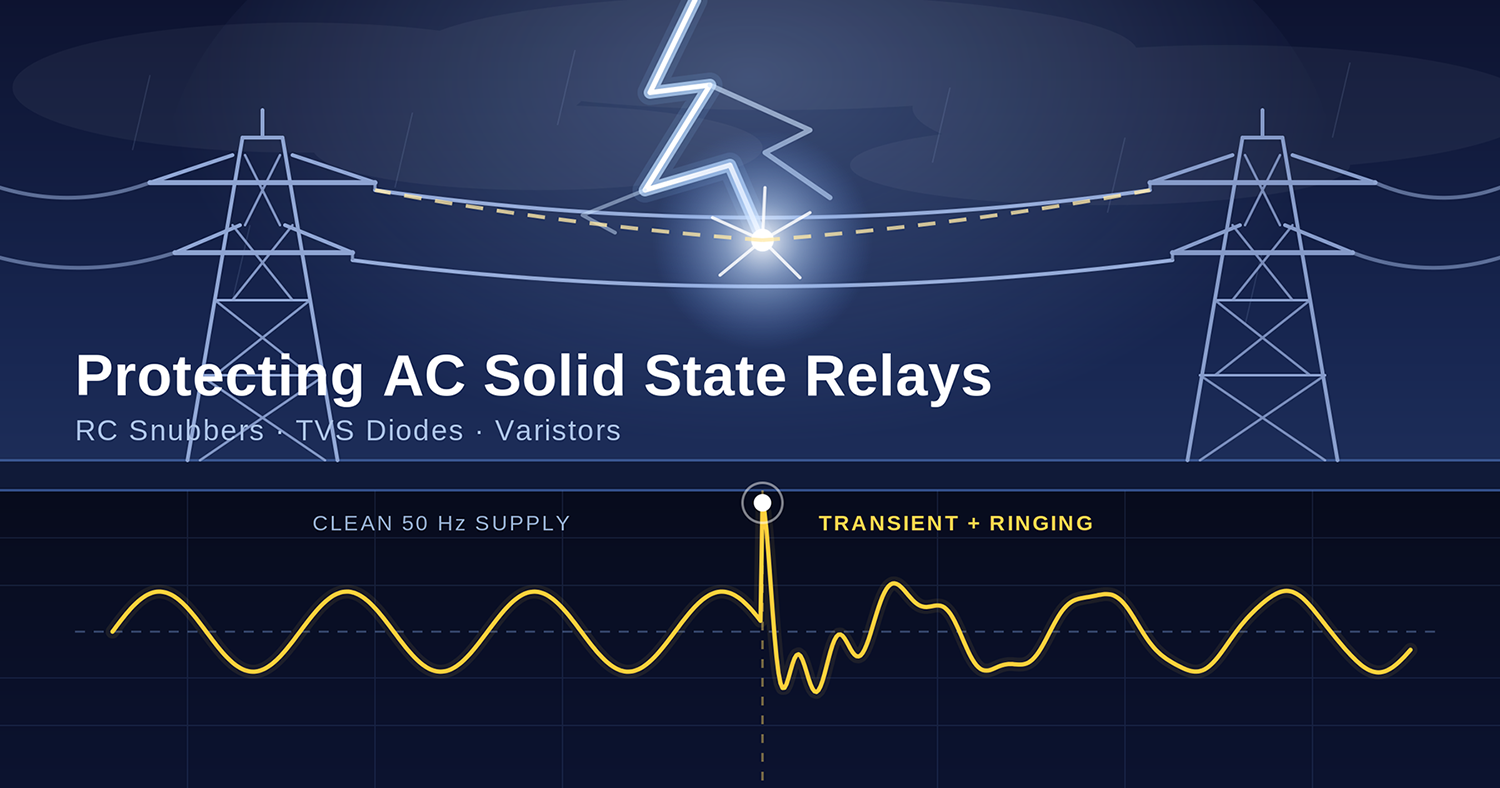
Before looking at protection methods, it helps to understand what you're protecting against. Transient voltages on AC circuits come from several common sources:
Inductive load switching
This is the big one. Every time a contactor, solenoid, motor, or transformer is switched off, the magnetic field in its coil collapses. That collapsing field generates a voltage spike that can be many times the normal supply voltage. The faster the current is interrupted, the higher the spike.
Power factor correction capacitor switching
When capacitor banks switch in or out on the distribution network — something utilities do routinely — they create fast-rising voltage transients that propagate through the supply.
Lightning and atmospheric discharge
Even indirect lightning strikes can couple significant energy into power lines. A direct strike nearby doesn't need to hit the building to cause problems.
Other SSRs and thyristor drives
When thyristors (including those inside other SSRs) switch, they generate high dv/dt transients on the line. In panels with multiple SSRs, one can upset another.
Arc flash during mechanical switch or circuit breaker operation
As contacts open under load, arcing generates broadband transients that travel back into the supply wiring.
Long cable runs
Cables have capacitance and inductance. Switching inductive loads at the end of long cable runs can produce reflected voltage transients that appear back at the SSR.
For a 240 V AC circuit, transient peaks of 1000–2000 V are not unusual in industrial environments. Many standard SSRs have output voltage ratings of 480 V or 600 V — not much margin when transients of that size appear on a 240 V line.
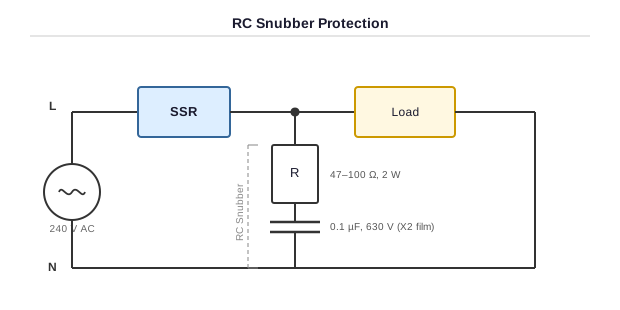
An RC snubber is simply a resistor and capacitor connected in series, placed across the SSR output terminals (in parallel with the load). It's a passive filter that limits the rate of voltage rise (dv/dt) across the SSR.
The key parameter for thyristor-based devices (triacs and SCRs) isn't just peak voltage — it's how fast the voltage rises. A triac can be triggered into conduction by a fast-rising voltage even when no gate signal is present, a phenomenon called dv/dt false triggering. The snubber slows that rise down.
Here's the mechanism: When current through an inductive load is interrupted, the inductance tries to maintain the current flow, which drives the voltage up. The snubber capacitor absorbs that energy, limiting the voltage spike and the rate of rise. The resistor damps the resonant ringing that would otherwise occur between the snubber capacitor and the line inductance — without it, you'd get a damped oscillation that could actually make things worse.
A common starting point for a basic snubber on a 240 V AC circuit is:
- Capacitor: 0.1 µF, rated for at least 630 V AC (or 1000 V DC). Use a film capacitor — X2 or X-rated types are designed for this application. Never use electrolytics.
- Resistor: 47–100 Ω, rated at 1–2 W minimum. Metal film or wirewound for reliability.
The exact values depend on load inductance and the SSR's dv/dt rating (found in the datasheet). Many SSR manufacturers publish recommended snubber values for their specific devices — always check the datasheet first.
The snubber goes directly across the SSR output terminals, as close to the SSR as possible.
Note: Because the capacitor is connected across the supply through the resistor, there will be a small leakage current flowing even when the SSR is off. In most industrial applications this is inconsequential, but it can cause problems with very low-power or high-impedance loads.
- Simple, low cost, and reliable — no active components
- Effective at limiting dv/dt, which is often the primary failure mode for triacs
- Works continuously without degrading (assuming the capacitor is rated correctly)
- Commonly built into many SSR designs already; an external snubber adds extra margin
- Does not clamp peak voltage — it only slows the rate of rise. Very large transients can still reach damaging levels
- Adds a small leakage current to the circuit
- Capacitor must be properly rated; a substandard capacitor in this location is a fire risk
- Values need to be matched to the load — a one-size-fits-all approach can result in inadequate protection
- Generates heat in the resistor under repeated transient conditions
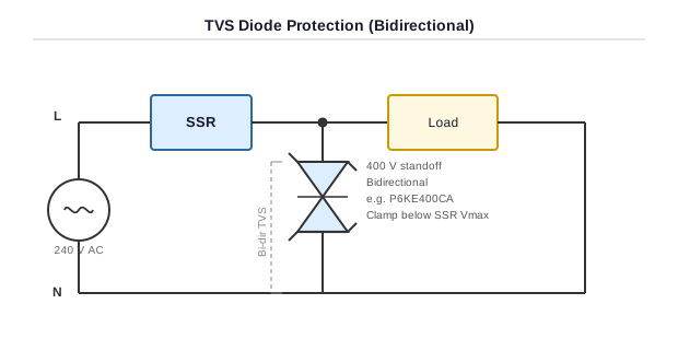
A TVS device is a semiconductor component — essentially a large, fast zener diode designed specifically for transient suppression. It sits across the circuit and conducts when the voltage exceeds its clamping voltage, diverting transient energy away from the protected device.
TVS devices are characterised by their extremely fast response time — typically in the picosecond range. This makes them effective against very fast transients (such as those from electrostatic discharge or fast-switching thyristors) where slower devices like MOVs can't react in time.
For AC applications you need a "bidirectional TVS" (also called a TVSbidirectional or TRIAC TVS), since the voltage alternates polarity. A unidirectional device will conduct on every negative half-cycle and destroy itself quickly.
The TVS is rated by its "standoff voltage" (the maximum voltage at which it remains non-conducting), its **breakdown voltage** (where it starts to conduct), and its **clamping voltage** (the voltage across it at peak rated current). It also has a peak pulse power rating (in watts), which describes how much transient energy it can absorb.
For a 240 V AC circuit, you'd typically select a bidirectional TVS with a standoff voltage above the peak AC voltage (240 V RMS = ~340 V peak), so a 400 V or 440 V standoff is common, with a clamping voltage at or below the SSR's maximum rated voltage.
- Extremely fast response — effective against the fastest transients
- Precise clamping voltage — you can select a device that clamps reliably below the SSR's damage threshold
- No significant leakage current when not conducting
- Available in a range of power ratings and packages
- Limited energy absorption capacity. TVS devices handle fast, low-energy transients well but can be destroyed by high-energy surges (such as nearby lightning). They are best used as a second line of defence behind a MOV, not as the sole protection on exposed installations.
- More expensive than MOVs or RC snubbers for equivalent voltage ratings
- Must be correctly specified — a TVS with too low a standoff voltage will conduct during normal operation and burn out; too high a clamping voltage won't protect the SSR
- Bidirectional types essential for AC — easy mistake to specify the wrong polarity type
- The device fails short-circuit when it exceeds its energy rating, which can cause other problems if not fused
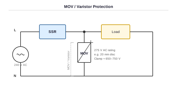
An MOV is a voltage-dependent resistor made from zinc oxide granules pressed into a disc. Under normal voltage, it has very high resistance and passes negligible current. When the voltage across it exceeds its clamping voltage, the resistance drops dramatically and it conducts heavily, clamping the voltage and absorbing the transient energy as heat.
MOVs are characterised by their "varistor voltage" (the clamping voltage at a specified test current), their "maximum continuous AC voltage" rating (V_AC), their "energy rating" in joules, and their "peak surge current" rating.
For a 240 V AC supply, a common choice is a 275 VAC or 300 VAC rated MOV (e.g., a 20 mm disc type). The 275 VAC rating means it's designed to operate continuously on a 240 V circuit with some headroom, and its clamping voltage will be typically 650–750 V at high surge currents — ideally below the SSR's rated surge voltage.
MOVs are placed directly across the SSR output terminals (or across the supply at the panel), as physically close to the SSR as practical.
- Excellent energy absorption capacity — far better than TVS for high-energy surges
- Low cost and widely available in standard disc sizes
- Self-contained — no additional components needed
- Well-suited to the sort of high-energy, lower-frequency transients common in industrial environments (motor switching, contactor chatter)
- MOVs degrade with each transient they absorb. Each surge causes a small permanent shift in characteristics. After many surges (or one very large one), the clamping voltage rises and eventually the device fails — often by going open circuit (losing protection) or, more dangerously, by going short circuit, which can start a fire. Thermal fusing or a varistor with built-in thermal protection is strongly recommended.
- Response time is slower than TVS — typically in the nanosecond range rather than picoseconds. Not effective against the fastest transients.
- Clamping voltage is not precise — it varies with manufacturing tolerances and degrades over time
- Must be rated for the supply voltage. Selecting an MOV with too low an AC voltage rating causes it to conduct during normal operation and overheat
In practice, the best protection often combines methods, since each covers weaknesses in the others:
This is the most common pairing for industrial AC SSR installations. The MOV handles high-energy transients and provides bulk clamping; the RC snubber controls dv/dt and protects against fast-rise transients that stress the SSR's gate triggering.- MOVs degrade with each transient they absorb. Each surge causes a small permanent shift in characteristics. After many surges (or one very large one), the clamping voltage rises and eventually the device fails — often by going open circuit (losing protection) or, more dangerously, by going short circuit, which can start a fire. Thermal fusing or a varistor with built-in thermal protection is strongly recommended.
- Response time is slower than TVS — typically in the nanosecond range rather than picoseconds. Not effective against the fastest transients.
- Clamping voltage is not precise — it varies with manufacturing tolerances and degrades over time
- Must be rated for the supply voltage. Selecting an MOV with too low an AC voltage rating causes it to conduct during normal operation and overheat
This combination provides good broadband protection. The MOV absorbs high-energy surges; the TVS clamps fast, low-energy spikes to a precise voltage. This combination is sometimes seen where very precise clamping is required.
Using all three on a sensitive or high-value installation is not overkill — the cost of three passive components is trivial compared to an SSR replacement and the downtime it causes.
A general installation note: protection devices should be mounted as close as physically possible to the SSR output terminals. Every centimetre of wire between the SSR and the protection component adds inductance that reduces effectiveness.
| Method | Best Against | Energy Handling | Response Speed | Degrades? |
|---|---|---|---|---|
| RC Snubber | dv/dt / false triggering | Low | Fast | No |
| TVS | Fast, precise voltage spikes | Low–Medium | Very fast | No (until destroyed) |
| MOV | High-energy surges | High | Medium | Yes — monitor and replace |
No single method covers every threat. For most industrial AC SSR applications, a properly sized MOV plus an RC snubber across the output terminals gives solid, cost-effective protection. Add a TVS where the fastest transients are a concern, or where load-switching events are frequent.
When in doubt, check the SSR datasheet — most reputable manufacturers will specify recommended protection components and give snubber values for typical loads. It's worth taking five minutes to read it before commissioning, rather than diagnosing a failed SSR six months later.
Practical Control Solutions supplies a range of AC solid state relays and transient suppression components. If you need help selecting the right SSR or protection devices for your application, get in touch.