

The control of Molybdenum Disilicide (MoSi2) heaters in high-temperature heating applications can be tricky due to their temperature-variable resistance. However, control can be successfully implemented through correct configuration and the use of suitable equipment.
This information is for general purposes only, please contact us on 03 9720 4522 or sales@practicalcontrol.com.au to discuss your specific requirements.
Characteristics of Molybdenum Disilicide Heaters
Molybdenum disilicide (MoSi2) heaters used in high temperature furnaces are amongst the most difficult heating elements to control due to their extremely low cold resistance. As they are virtually a short circuit at cold startup, control systems must be designed accordingly to limit maximum current during this phase of operation. Resistance from cold to working temperature can vary by a factor of 10.
At low temperatures molybdenum heaters are brittle and can be damaged by electromagnetic forces caused by excessive current. At temperatures above 1200°C they become ductile.

The resistance of Molybdenum Disilicicide heaters does not change significantly over time; unlike Silicon Carbide heaters, their high temperature counterparts, they consequently do not require any voltage "headroom" or reserve to allow for element resistance increase due to ageing.
Power Control of Molybdenum Disilicide (MoSi2) Heaters
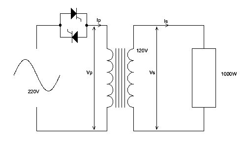
Molybdenum disilicide heaters normally require a low voltage power supply and are typically coupled to the mains via an isolation transformer, with a thyristor regulating power to the heaters through the transformer primary.
Thyristors used to control molybdenum disilicide heaters are operated in phase control mode (i.e. with constantly variable voltage) rather than burst control mode (which outputs bursts of full mains voltage with on time/off time proportional to the control input signal). Using burst control with molybdenum heaters would result in extremely high peak currents when used on cold heaters. Click here for a demonstration video illustrating the two firing modes.
In addition to operation in phase control mode, thyristors used for the control of molybdenum heaters must have an electronic current limit feature. CD Automation's Revo CL, CD3000E and Multidrive thyristors all have a fast current limit feature of this kind and thus can be safely used with MoSi2 heaters.

Output current is measured by the thyristor and fed back internally. Because phase angle firing results in a non-sinusoidal current waveform, the current feedback to the thyristor must be true RMS, as should all instrumentation measuring current in the system. It should be noted that measuring average current rather than RMS will result in significant errors.
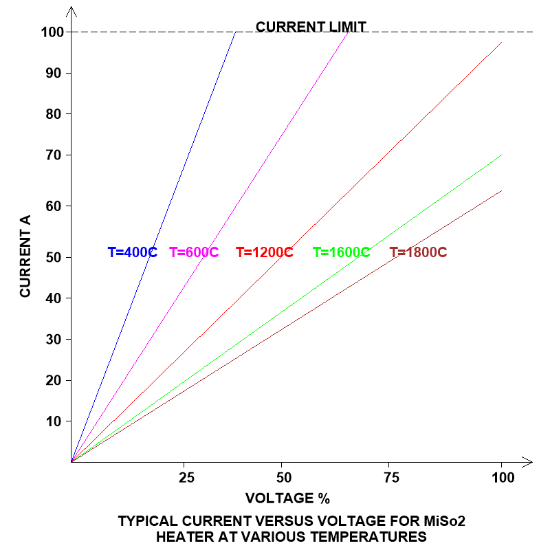
On a cold start up the temperature controller will be calling for maximum heat and will thus attempt to wind the thyristor fully on to maximum voltage. This would certainly cause a massive over-current situation due to the heater's extremely low cold resistance. This is where the thyristor takes control. The thyristor's current limit feature drops its output voltage to limit output current to a preset maximum. As the graph below demonstrates, at 400°C only around 30% of available voltage can be used before the thyristor's current limit is reached. As the temperature of the MoSi2 heater increases its resistance also increases, meaning that the thyristor can apply more and more voltage to the heaters whilst maintaining the current limit.
As the heater approaches its working temperature its resistance increases to a point where there is enough heater resistance to self-limit maximum current without the aid of the thyristor's electronic current limit. At this point, for a constant voltage, the power applied to the heaters is V2/R and reduces with temperature, so the heating process effectively self regulates.
The thyristor should also have an internal linear ramp function that gradually increases the voltage applied to the heaters. This helps to minimise cold heater inrush currents by applying the voltage to the MoSi2 heaters slowly and smoothly. The ramp function should operate each time the supply to the MoSi2 heaters is interrupted and then reconnected-- for example, when a door interlocked supply contactor drops out and in after the furnace door is opened and closed.
Conclusion
Furnace design starts by determining the power required and selecting molybdenum disilicide (MoSi2) heaters to meet that requirement. Once the power and maximum required voltage of the heater element arrangement is known, a transformer with the appropriate VA rating, primary voltage and secondary voltage can be selected. A thyristor can then be selected to control the heaters. The thyristor is normally placed on the transformer primary side, as this allows the use of a lower current device (with consequent lower cost and lower heat dissipation) than would be required if it was placed on the secondary.
Essential features of the thyristor controlling the MoSi2 heaters are phase control, fast electronic current limit and ramp function.